System Description
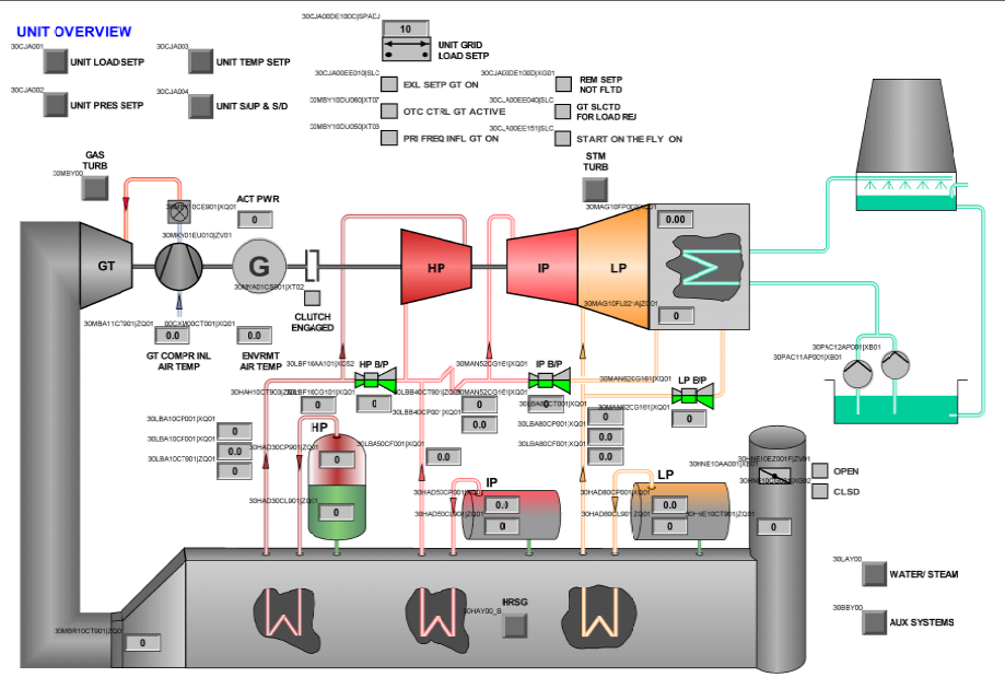
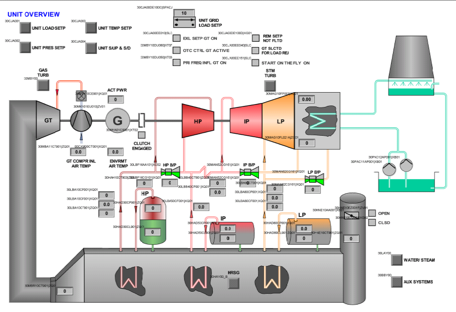
The exhaust gases from the Gas Turbine are used in a Heat Recovery Steam Generator (HRSG) to produce steam, which is then directed to the Steam Turbine.
Gas Turbine Siemens SGT5 4000F (Versão 6) (50 Hz)
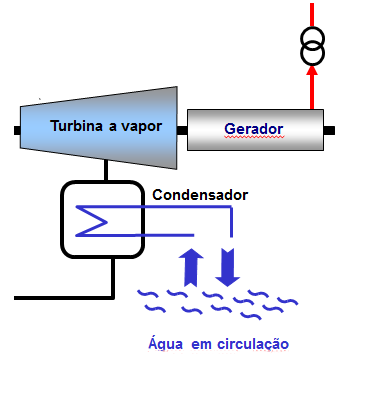
Steam Turbine / Condenser Siemens SST5 3000, SCon1000 (AP – Tipo H30 25 25 TPL / MI+BP – Tipo H30 25 25 TPL)
Generator – Siemens SGEN5-2000H (Hydrogen Cooled – 37ºC)
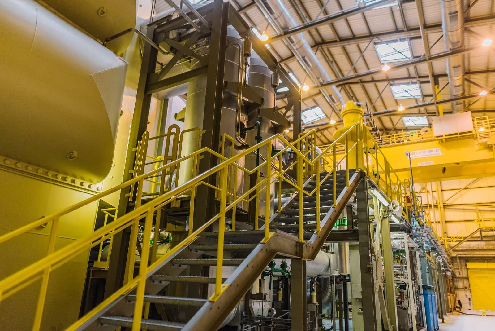
Boiler – NEM Industrial & Utility Boilers, Benson design with three pressure levels (HP, IP and LP)
SPPA-T3000 Control System
Auxiliary Equipment
Cooling Towers
Electrical Equipment
It was designed to supply electricity efficiently and safely, at low cost and with high reliability. Its features were carefully considered to achieve an optimal balance between capital costs, equipment efficiency, and operational and maintenance benefits.
Emissions from natural gas combustion are minimised through a hybrid low-NOx combustion system.
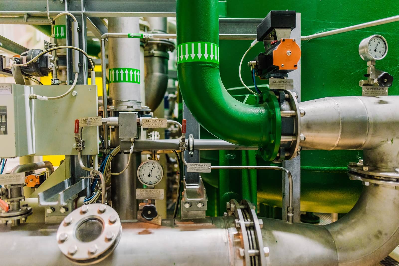
Several pieces of equipment are cooled through a closed cooling water circuit, which is itself cooled by the main cooling system through heat exchangers.
The Gas Turbine, Generator, and Steam Turbine are arranged on a single shaft line and connected through a synchronous self-shifting clutch (SSS clutch). The generator is located between the two turbines.
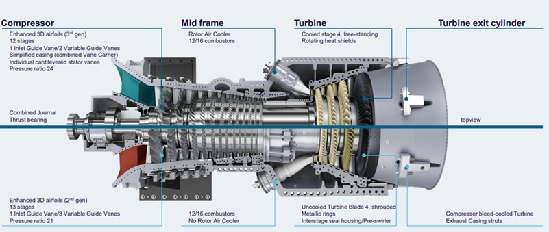
Gas Turbine provides a uniform exhaust gas temperature profile across the entire diffuser section. This is achieved through the 24 hybrid burners forming a continuous flame ring, thereby eliminating hot and cold spots.
The hybrid burners limit thermal NOx formation without the need for steam or water injection, based on a design and operational experience developed since 1986.
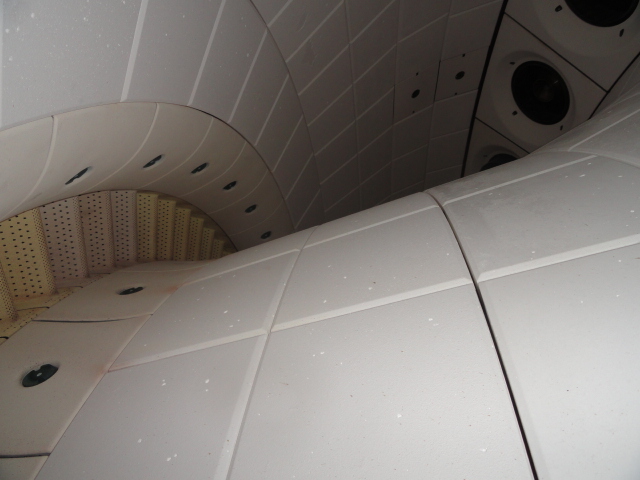
Low NOx and CO emissions
Low pressure loss
High operational flexibility
Symmetrical design using a reduced number of heat shield shapes
Optimum number and size of burners
Compact design with good accessibility
The hydrogen-filled generator casing is a gas-tight and pressure-resistant construction, equipped with terminal shields at both ends.
The three-phase winding inserted into the stator core is of a two-layer transposed-bar design. The winding is vacuum impregnated together with the stator core.
The generator rotor shaft is vacuum-forged and fitted with two radial bearings located in the terminal shields.
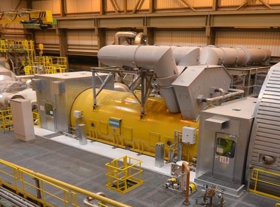
Hydrogen circulates within the Generator in a closed circuit by means of axial fans located near the radial bearings.
The Generator gas system includes the equipment required for filling, purging, and operating the generator with air, purge gases, and hydrogen.
An excitation transformer is used to supply excitation current for the auxiliary power systems. A static frequency converter is used for starting the Gas Turbine / Generator train, supplying power to the Generator so that it can operate as a motor during start-up.
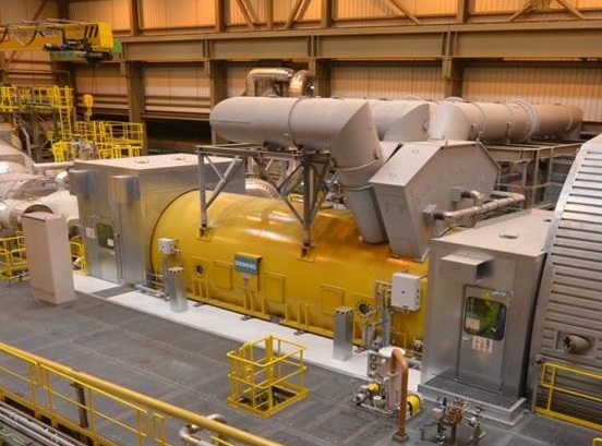
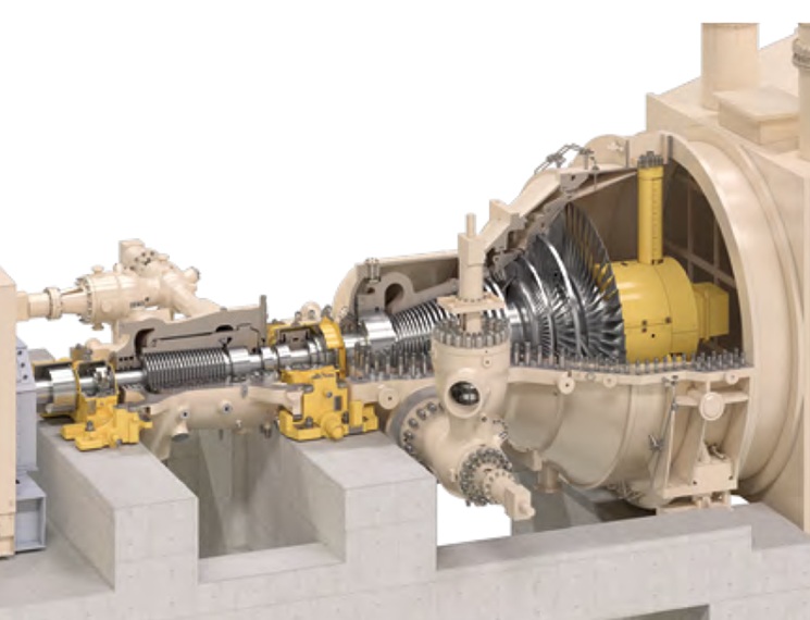
The shafts are rigidly coupled through integral flanges. Each Steam Turbine is equipped with a combined stop and control valve for high-, intermediate-, and low-pressure steam admission. These valves are fitted with electro-hydraulic actuators.
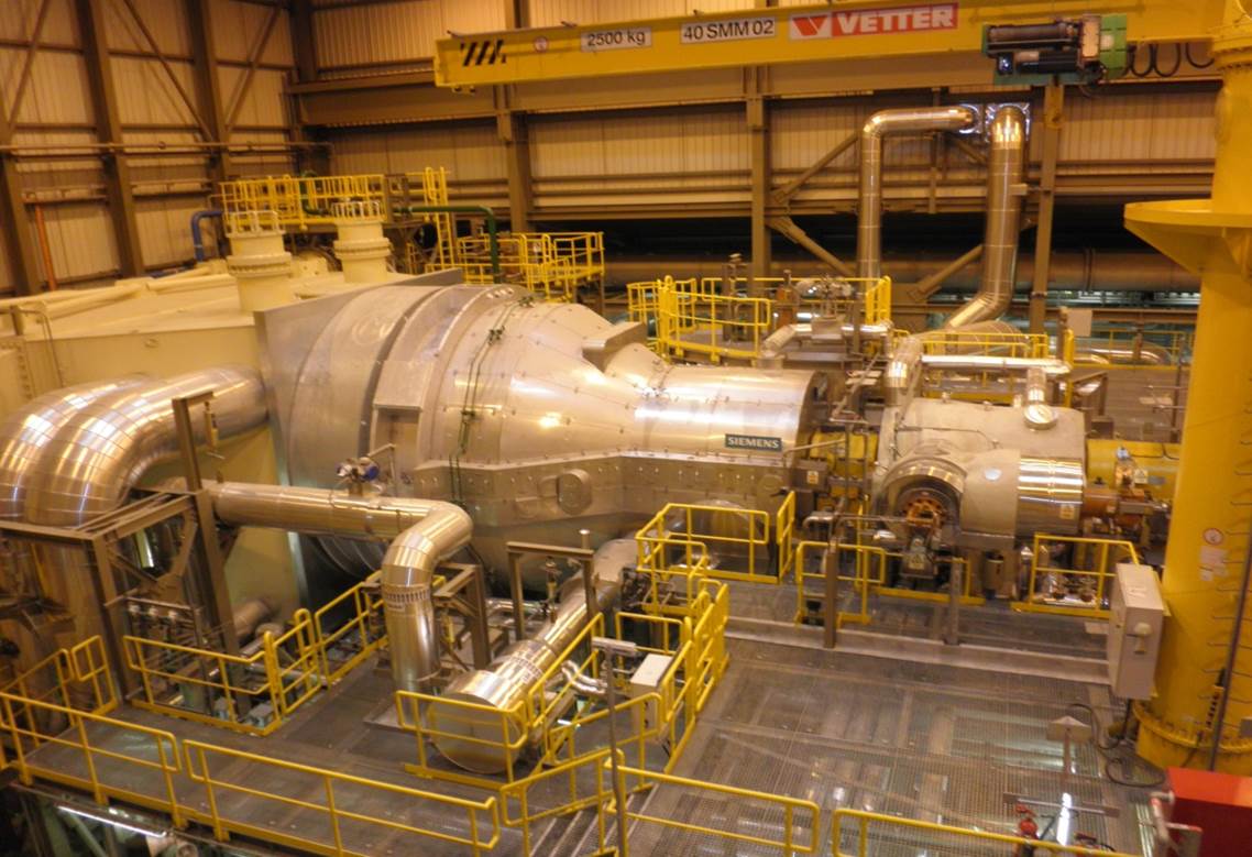
A common lubrication system is provided for the Gas Turbine, Steam Turbines, Generator, and Clutch. During normal operation, oil is supplied by an electric pump.
A synchronous clutch is located between the Generator and the High Pressure (HP) Steam Turbine and transmits the torque generated by the Steam Turbines to the Generator.
The clutch increases operational flexibility and allows faster start-up of the generating unit.
The Steam Space and Condensate Hotwell are constructed of steel.
The condenser is supported by a foundation underneath. The Steam Space has a rectangular shape in order to ensure optimum utilization of the available steam volume.
Extraction of non-condensable gases is carried out by 2 × 100% liquid ring vacuum pumps.
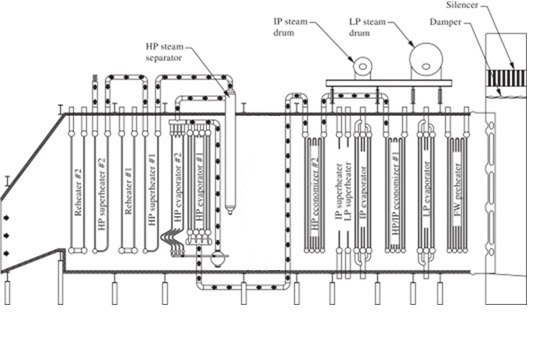
An integrated condensate preheater improves combined cycle efficiency by using the energy from the exhaust gases to preheat the condensate before it passes through the feedwater pump and low-pressure circuit.
The boiler is designed for outdoor installation and does not include a bypass stack between the Gas Turbine and the boiler. The boiler is equipped with an exhaust duct connected to the stack.
It is based on open hardware and software technology standards, thereby benefiting from continuous innovations in microelectronics.
Elecgas offers free educational visits to the Combined Cycle Power Plant. Shall we schedule yours?